
Soldering Iron Temperature Guide for PCB Repair: Leaded vs Lead-Free
Choosing the right soldering iron temperature is not about using the hottest setting possible. Good PCB repair depends on solder alloy, tip geometry, thermal mass, flux activity and efficient heat transfer.
ANSWER
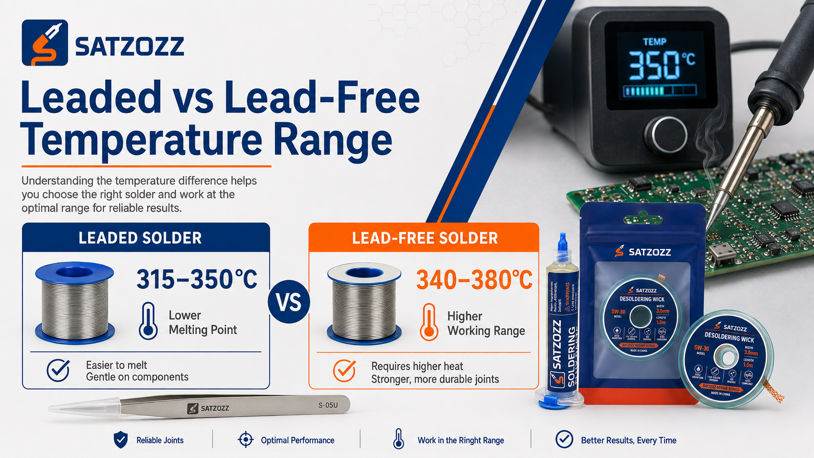
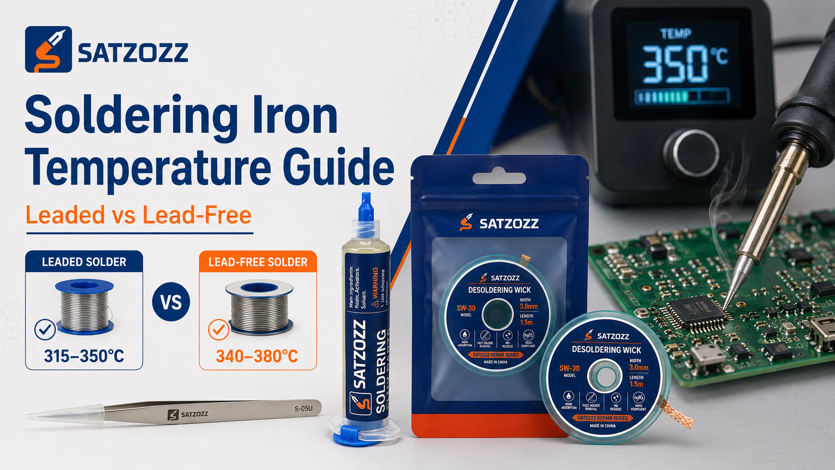
For many PCB repair jobs, around 315–350°C is a practical starting range for leaded solder, while approximately 340–380°C is commonly used as a starting range for lead-free solder. These are not universal settings. Use the lowest temperature that produces fast, clean solder wetting without forcing you to hold the iron on the PCB for too long.
One of the most common mistakes in electronics repair is treating soldering iron temperature as a single fixed number.
A temperature that works perfectly for a small 0402 pad may perform poorly on a large ground plane, connector shield or desoldering braid.
The correct setting depends on how efficiently heat moves from the soldering station through the tip and into the solder joint.
What Temperature Should You Set a Soldering Iron To?
Start with the solder alloy, then adjust for the actual repair.
Leaded Solder
Tin-lead solder melts at a lower temperature and generally wets copper more easily than common lead-free alloys.
For small PCB pads and normal hand soldering, begin near the lower part of the range and increase only when the joint requires more thermal energy.
Lead-Free Solder
Lead-free solder normally has a higher melting range and can require more efficient heat delivery.
Do not automatically solve slow wetting by increasing the station to maximum temperature. Tip size and thermal recovery are equally important.
Why Is Soldering Temperature Higher Than the Solder Melting Point?
Melting temperature and working tip temperature are not the same thing.
Tin-lead solder such as Sn63/Pb37 melts at approximately 183°C, while many common lead-free SAC alloys melt around 217–221°C.
However, a soldering iron must transfer enough thermal energy through the tip into:
- The PCB copper pad
- The component lead
- The existing solder
- Ground planes
- Nearby copper structures
Because these surfaces absorb heat, the soldering station is normally set considerably above the solder alloy melting temperature.
Practical PCB Soldering Temperature Chart
These ranges are useful starting points, not absolute limits.
| Repair Task | Typical Starting Range | Key Consideration |
|---|---|---|
| Small leaded SMD joint | 300–330°C | Use a fine but thermally capable tip. |
| General leaded PCB soldering | 315–350°C | Good general starting range. |
| Small lead-free SMD joint | 330–360°C | Use good flux and proper tip contact. |
| General lead-free PCB soldering | 340–380°C | Increase gradually only when necessary. |
| Large connector or ground plane | 350–380°C+ | A larger tip may help more than extra temperature. |
| Desoldering wick | 350–380°C | Heat must pass through the copper braid first. |
How to Find the Correct Temperature for Your PCB
Use solder behavior instead of relying only on the display number.
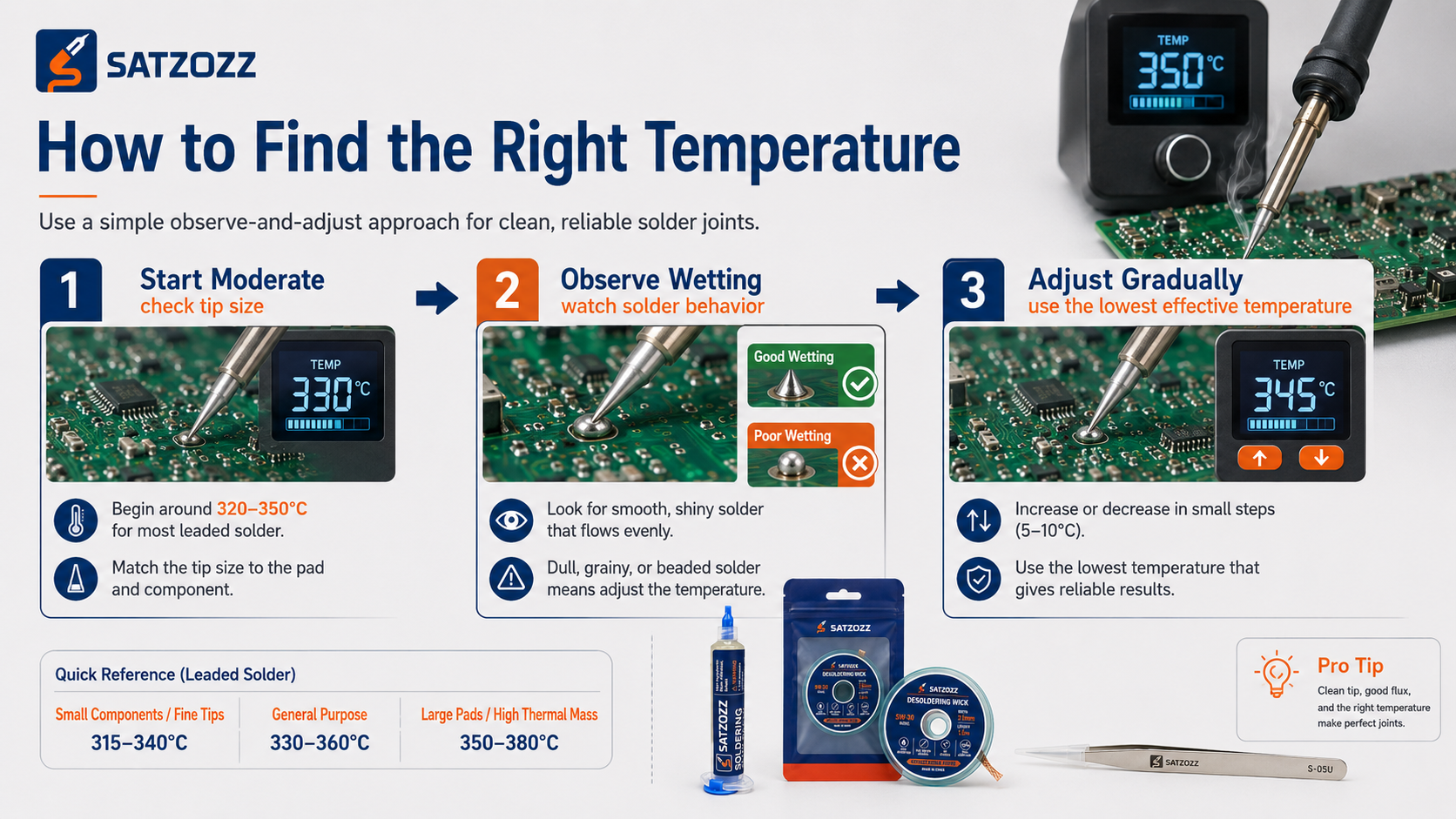
Start Moderate
Begin near the lower or middle part of the recommended range for your solder alloy.
Observe Wetting
The solder should melt and flow within a short controlled heating cycle.
Adjust Gradually
If heat transfer remains poor, check tip size and cleanliness before increasing temperature.
Signs Your Soldering Iron Temperature Is Too Low
Low temperature can be just as damaging as excessive temperature.
Solder Takes Too Long to Melt
The joint absorbs heat faster than the tip can supply it.
Solder Forms a Ball Instead of Wetting the Pad
Poor wetting can result from low joint temperature, oxidation or insufficient flux.
Before increasing heat, confirm that the PCB pad and tip are clean.
Also read How Much Soldering Flux Should You Use for PCB Repair?
Desoldering Wick Does Not Absorb Efficiently
Heat must travel through the copper braid before reaching the solder. If thermal transfer is insufficient, the solder remains partly solid.
Learn more in Do You Need Flux When Using Desoldering Wick?
Signs Your Soldering Iron Temperature Is Too High
Excess temperature can damage both the flux and the PCB.
- Flux immediately burns or turns very dark.
- The solder mask begins discoloring.
- The soldering tip oxidizes rapidly.
- The PCB pad becomes loose or begins lifting.
- Plastic connectors soften or deform.
- Flux spits or bubbles aggressively.
- Solder wetting becomes worse after prolonged heating.
If flux becomes dark, sticky or carbonized, read Why Does Soldering Flux Turn Brown or Sticky?
If flux pops or sprays during heating, see Why Does Soldering Flux Bubble or Spatter?
Tip Size Often Matters More Than Another 20°C
Temperature is only one part of heat delivery.
Small SMD Pads
Gives excellent access and visibility but has limited thermal mass.
General PCB Work
Larger contact area can transfer heat faster than a needle point.
Ground Planes & Connectors
Provides additional thermal capacity for heat-intensive joints.
If a fine tip struggles to heat a large pad, changing to a larger contact area is often better than increasing the station temperature dramatically.
What Temperature Should You Use With Desoldering Wick?
Desoldering braid adds another thermal load between the iron and solder.
Desoldering wick is braided copper, so it absorbs heat as well as solder. The soldering tip must first heat the braid before the solder underneath becomes fully molten.
For many PCB repair jobs, approximately 350–380°C is a practical starting range when using solder wick.
However, before raising temperature:
- Use a fresh section of braid.
- Add a controlled amount of flux.
- Use a tip wide enough to contact the braid effectively.
- Match the wick width to the PCB pad.
- Do not drag the braid over the PCB.
For solder-removal technique, see How to Clean PCB Pads After Removing Components .
If you are repairing accidental shorts, also read How to Remove Solder Bridges on a PCB Safely .
Temperature Control for Fine-Pitch and SMD Microsoldering
Small components need precision more than excessive heat.
Fine-pitch ICs, 0201 components, 0402 components and small PCB pads can heat quickly because very little material is involved.
Use:
- A clean, properly tinned tip
- Suitable magnification
- Controlled flux application
- Short heating cycles
- Fine precision tweezers
- The lowest effective soldering temperature
Avoid holding the soldering iron on a small pad simply because the tip is too fine to transfer enough heat efficiently.
SATZOZZ Tools for Controlled PCB Repair
Temperature works together with flux, solder-removal tools and precision handling equipment.
NC559 Flux Kit
No-clean flux for localized PCB soldering, SMD rework and microsoldering.
View SATZOZZ Products →Desoldering Wick
Copper braid in multiple widths for pad cleaning, bridge removal and solder rework.
View Desoldering Wick →S-05U Precision Tweezers
Ultra-fine precision tweezers for component placement and PCB microsoldering.
View S-05U Tweezers →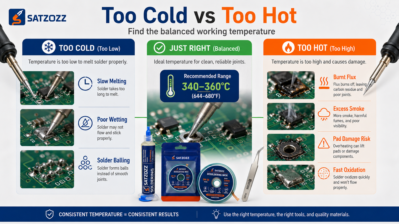
Soldering Iron Temperature Questions
Quick answers for PCB repair and microsoldering.
What is the best soldering iron temperature for PCB repair?
There is no single best temperature. Around 315–350°C is a useful starting range for many leaded solder jobs, while 340–380°C is a practical starting range for many lead-free PCB repairs.
Is 350°C too hot for PCB soldering?
Not necessarily. 350°C is commonly used for PCB repair, but whether it is appropriate depends on solder alloy, tip size, PCB thermal mass and heating time.
What temperature should I use for lead-free solder?
Approximately 340–380°C is a practical starting range for many lead-free hand-soldering applications. Use the lowest setting that produces efficient wetting.
What temperature should I use for 63/37 solder?
Many PCB repair jobs using 63/37 solder can begin around 315–350°C, with lower settings often suitable for small SMD joints.
Why does solder not melt even when my iron is hot?
The problem may be poor tip contact, oxidation, insufficient thermal mass, a tip that is too small or a large PCB ground plane absorbing heat faster than the iron can deliver it.
Should I increase temperature when desoldering wick does not work?
Not immediately. First check braid width, flux, tip cleanliness and contact area. A larger soldering tip may improve heat transfer more effectively than simply increasing temperature.
Can excessive soldering temperature lift PCB pads?
Yes. Excessive temperature and prolonged heating can weaken pad adhesion and increase the risk of lifted pads, damaged solder mask and nearby component damage.
Why does flux turn dark when soldering?
Flux darkens as it is heated. Very dark, burnt or carbonized residue can indicate excessive temperature, prolonged heating or repeated rework.
Better PCB Repair Starts With Controlled Heat
Match soldering temperature with the correct tip, flux and repair tools instead of relying on maximum heat.
Explore SATZOZZ Repair Tools Request Sample & Quote